Jtag nokia lumia 620
JTAG Nokia Lumia 620
The Nokia Lumia 620 is a Windows based smartphone. As of this writing (2014AUG28), I am unaware of any method other than JTAG to acquire a physical image of the NAND on a Nokia Lumia 620.
For the purpose of this document, a Lumia 620 was disassembled, read via JTAG, and reassembled.
Getting Started
What you need to dump the NAND:
- A RIFF Box
- Soldering skills and ultra-fine tip soldering iron (a JTAG jig may be available).
- A DC Power supply capable of supplying 3.7V/1.30A output. The power supply used for this was an U8002A DC Power Supply.
- A hot air re-work station. The hot air re-work station used for this was an LF-852D Hot Air Station.
NAND Dump Procedure
- Disassemble the phone down to the PCB.
- Connect the RIFF JTAG Box to the PC via USB.
- Connect the RIFF JTAG Box to the PCB via the JTAG pins.
- Connect the PCB to the DC power supply.
- Start the "RIFF JTAG" software.
- Enable the power on the DC power supply.
- Power the phone via the power button.
- Dump the NAND via the RIFF software.
Instructions for dis-assembly can be found on Internet but it can be summarized as follows:
* Remove the rear cover using a case opening tool (guitar pick)
* Remove the battery.
* Remove the 6 x T-4 Torx screws.
* Remove the 2 plastic covers protecting the mainboard.
* Disconnect the 2 ribbon cables that are connected to the main-board.
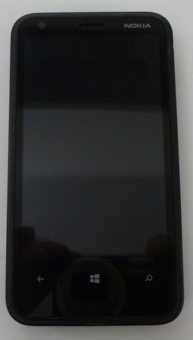
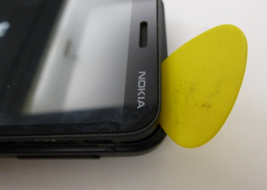
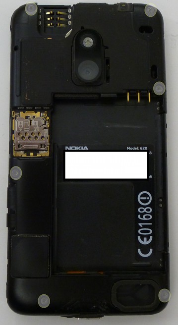
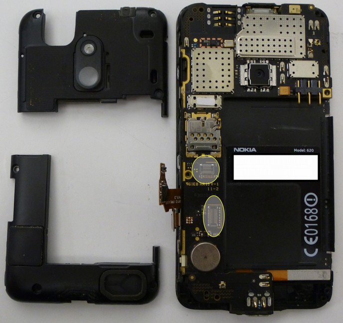
* Separate the main-board from the phone.
* The JTAG TAPs on the Lumia 620 are located under an EMI shield above the SD card slot. The shield was removed using a hot air re-work station at a temperature of approximately 350 centigrade.
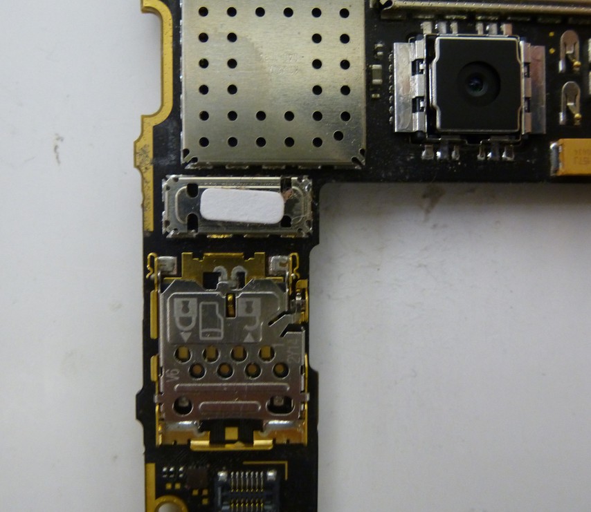
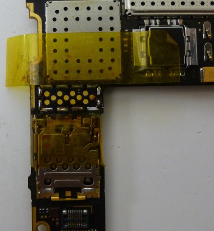
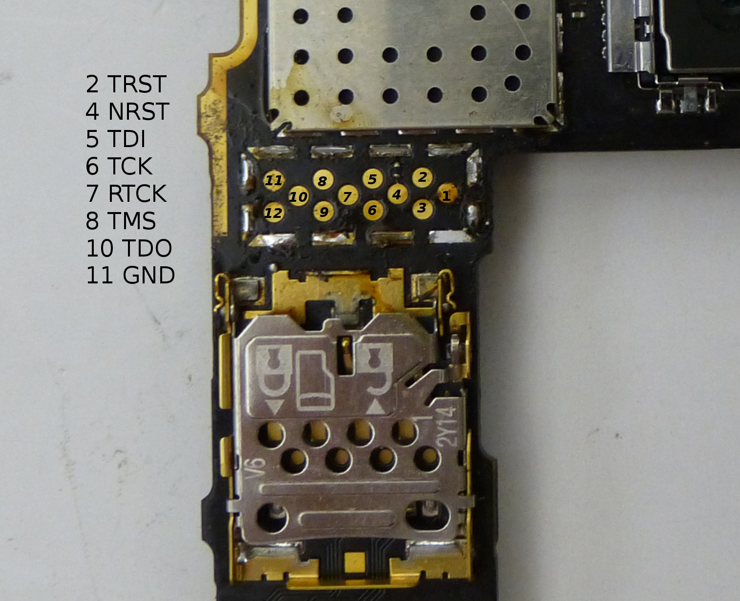
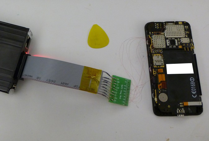
* Solder connecting wire to the JTAG TAPs as follows. I used 0.040 gauge magnet wire to connect an adapter that was inserted into the 20 pin ribbon cable supplied with the RIFF box.
* Re-connect the LCD display connector to the mainboard.
* Connect the PCB battery terminal connections to the DC power supply. The positive (+) connection is the outermost pin (1) and the negative (-) pin is the outermost pin (3). You can configure your power supply to match the battery specifications which in this case is 3.7V and 1.30A but do not apply power at this time.
* Now we can start the RIFF JTAG software, configure it for the LG E960, and connect the phone to the RIFF box. See the picture for more detail.
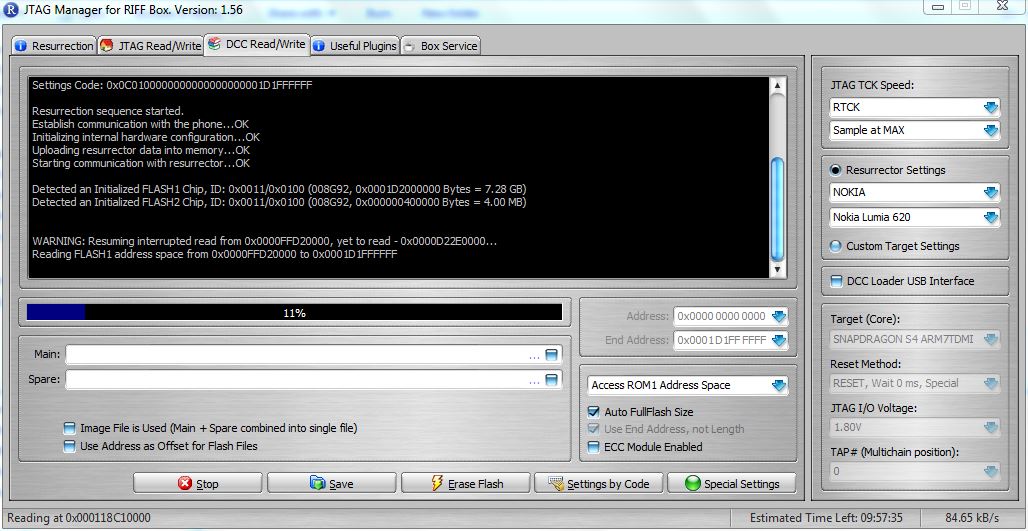
* Apply power from the DC power supply to the phone and turn the phone on using the button on the side of the PCB. After powering the phone on, select "READ" under the "DCC Read/Write" tab. If all goes well the "READ" button will become the "STOP" button and the phone will begin reading. If not, the RIFF software provides troubleshooting steps that should be taken to assist in diagnosing some of the issues you may experience.